For most electrical control designers, the "Start-Stop" or "Self-Holding Circuit" is the bread and butter circuit.

Pressing momentary-contact Push Button "Start" activates the coil of Contactor "K", closing auxilliary contact "K", which holds the circuit in the "On" state even after removing one's finger from the Start Button. Pressing P.B. Stop de-activates the circuit. This is the basic circuit, to which unlimited "Stop"s may be added in series to the P.B. Stop, and unlimited "Start"s may be added in parallel with the P.B. Start. These circuits can be found everywhere, and for many good reasons.
Essentially we're converting a pulse signal to a steady signal.
But what if we need the opposite: to convert a steady signal to a pulse? It's not so intuitively obvious why we would ever need such a circuit, but I'll give some examples later. Meanwhile let's give a warm welcome to the One-Shot Circuit.
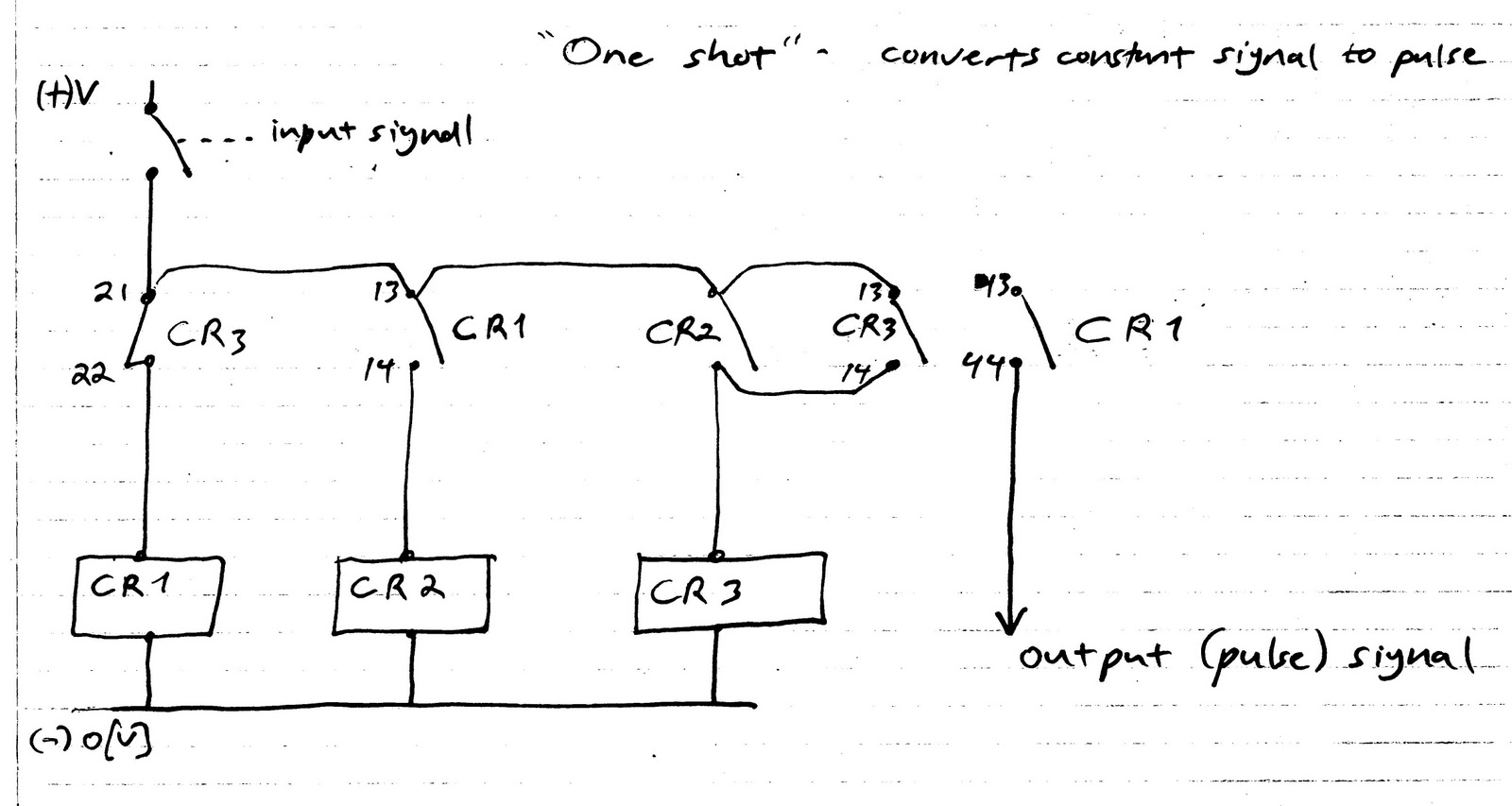
A steady input signal activates Control Relay 1. CR1's Normally Open Contact 13-14 closes, activating CR2. CR2's N.O. contact closes, activating the coil of CR3, which is then "held" by its own auxilliary contact 43-44. CR3's Normally Closed contact 21-22 opens, deactivating CR1. In the blink of an eye, CR1 has been activated and deactivated: voila, a pulse! Note that the input signal remains steady, and CR3 remains activated, preventing anymore output pulses. Only after the steady input signal is removed, is the circuit reset.
So, many years ago, I wanted to install a floodlight in my backyard. My first thought was to use a light-sensitive switch (photocell) to turn the floodlight on at night and off during the daytime.

But then I thought, "Maybe I should turn it off as I go to bed.

But then I thought, "But now I'll have to remember to close the switch again in the morning when I get up, or else the light won't turn on next evening. More than likely, I'll forget. You see the problem.
So then I thought, "What if I replaced the switch with a Start-Stop Self-holding-circuit arrangement. Then I wouldn't need to remember anything in the morning.

But it won't work. The PB Stop will turn off the light, but the photo cell (remember, it's still dark outside), will turn it back on again once I release the button. And it doesn't matter where in the circuit I choose to locate the PB Stop button. It just won't work.
And then, I had my epiphany: One-shot. Steady signal from the photocell in, pulse out.
Now for clarity's sake, let's replace our One-Shot circuit schematic with a simple block diagram:

Then the combined circuit will look something like this.

You see how the One-Shot block replaces the Start Push Button in a "regular" Start-Stop Self-Holding Circuit? The circuit works like this: When evening falls the photocell "contact" closes, sending a steady signal to the One-Shot block until morning. The One-Shot converts the steady signal to a pulse, which meshes with the overall Self-Holding circuit as a Momentary Start pulse. Pushing the PB Stop anytime during the night will extinguish the flood light, without interfering with the One-Shot.
All that remains to get the full picture is to replace the Block Diagram with the One-Shot circuit schematic as diagrammed earlier in this article. I will leave that to you, my engineering brothers and sisters. I'm sure that if you grasp this concept, you will find many applications for it in the industrial world. It's true that it is possible to buy multi-purpose timers that have a One-Shot function, and it is also true that any PLC will also have the function, usually by another name. What can I tell you? Sometimes "primitive" is best. Have a good one.